In Part 2 we learned how to insert inspection between subnets inside a single VPC with clean, symmetric paths. This post takes the same mindset across VPC boundaries in the same Region. We will first establish a direct path through Transit Gateway as a baseline, then introduce a centralized inspection VPC and harden symmetry so stateful controls behave predictably. By the end, you will know where to place inspection and how to keep both legs of a flow on the same hop.
Inter-VPC east-west traffic is service-to-service communication that crosses VPC boundaries but stays inside one AWS Region. Teams usually start here after securing intra-VPC paths because the next set of questions appears between VPCs: where should inspection live, how do we steer packets through it without hairpins, and how do we guarantee that forward and return traffic hit the same device.
Transit Gateway is the fabric that connects spoke VPCs to each other and to a dedicated inspection VPC. The inspection tier can be a Gateway Load Balancer endpoint fronting third-party appliances or an AWS Network Firewall endpoint if you prefer a managed experience. We stay within single Region, we do not cover internet ingress or egress here, and we assume non-overlapping CIDRs with standard multi-AZ layouts in each VPC.
The objectives are clear: keep visibility and enforcement consistent across VPC boundaries, preserve predictable latency by staying zonal where possible, and avoid asymmetric routing that breaks stateful devices. In this post, we’ll cover one main pattern that introduces a centralized inspection VPC on the path and then locks in symmetry using Transit Gateway appliance mode plus AZ affinity. Along the way, we will point out where Cloud WAN can implement the same idea with policy-driven insertion, but the primary walkthroughs use Transit Gateway so you can apply them in any standard environment today.
By the end of this article, you will have a clear, repeatable inter-VPC design that you can lift into any Region.
- A baseline fabric: a simple Transit Gateway setup that connects two spoke (or more) VPCs so you can see the uninspected east-west path and use it as a reference point.
- A centralized inspection path: a dedicated Inspection VPC inserted between the spokes, using either Gateway Load Balancer endpoints with third-party appliances or AWS Network Firewall endpoints. Traffic will be steered through this hub in a way that keeps latency predictable and avoids hairpins.
- Symmetry guardrails: a concrete approach to keep both directions of every stateful flow on the same inspection hop using Transit Gateway appliance mode and Availability Zone affinity. We will show where symmetry typically breaks and how to prevent it.
- Cloud WAN note: a short mapping that shows how the same centralized pattern can be built with Cloud WAN using policy-driven service insertion, plus guidance on when to choose Cloud WAN versus Transit Gateway for operations at scale.
- Placement decisions: practical guidance on placing inspection in relation to ALB or NLB inside the spokes, what that means for client IP visibility and TLS decryption, and how to stay zonal to control cost and latency.
- Operational baseline: the minimum logs and metrics you should enable on day one, what to watch for in pass to drop ratios and attachment throughput, and how to recognize hidden cross-AZ charges before they surprise you.
Baseline fabric: AWS Transit Gateway
In this series, Transit Gateway (TGW) is the hub that connects all VPCs. Each VPC has a TGW attachment. That attachment is a pair of ENIs in TGW subnets inside the VPC. TGW itself has its own route tables. You can associate different attachments to different TGW route tables and control forwarding in the hub.
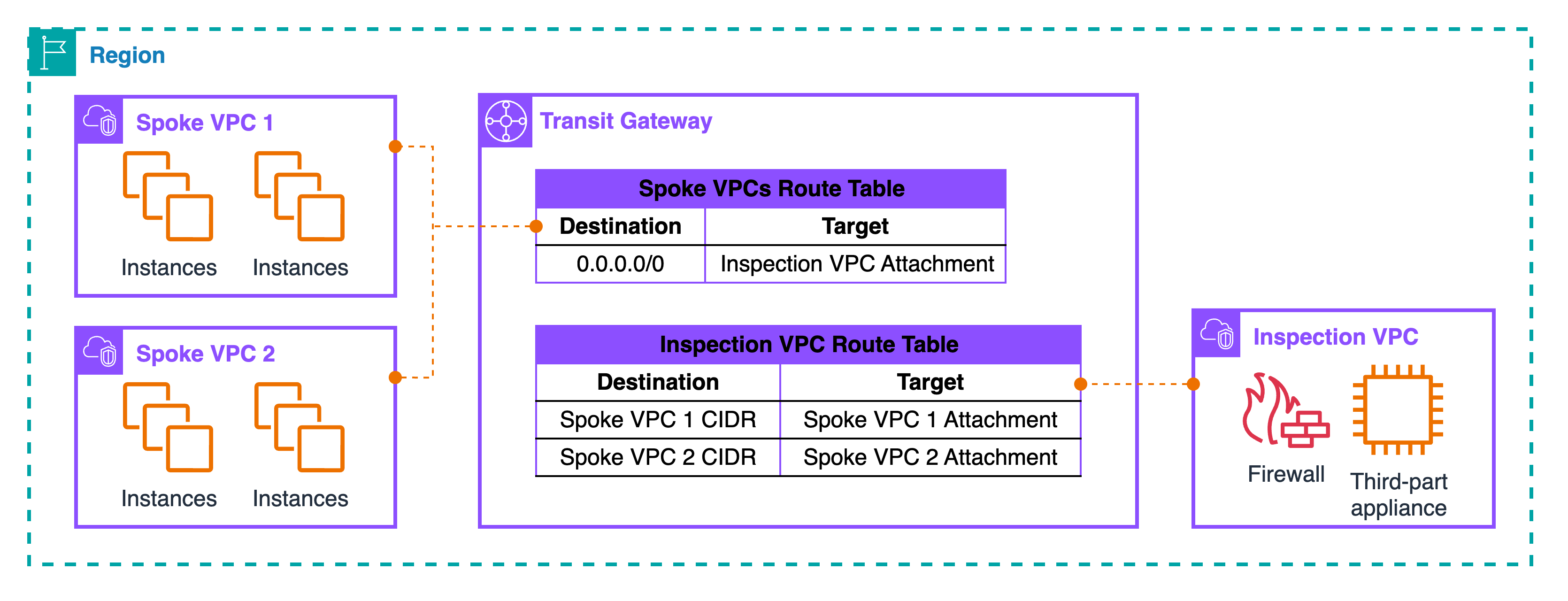
Spoke VPC 1 and Spoke VPC 2 each attach to TGW. Their attachments are associated with a TGW route table named “Spoke VPCs Route Table.” In that table, there is a default route 0.0.0.0/0 that points to the Inspection VPC attachment. This one line is the trick: “anything that is not local to my spoke” goes to the inspection VPC. The Inspection VPC attachment is associated with a different TGW route table named “Inspection VPC Route Table.” In that table, you add specific routes for each spoke CIDR. For example: “Spoke VPC 1 CIDR → Spoke VPC 1 attachment” and “Spoke VPC 2 CIDR → Spoke VPC 2 attachment.” With this split, TGW always sends spoke traffic into the inspection VPC first, and the inspection side sends the packet out to the correct spoke after inspection.
A source in Spoke VPC 1 needs to reach a target in Spoke VPC 2. The subnet routes in Spoke 1 send “remote VPC CIDRs” to TGW. The packet enters TGW on the Spoke 1 attachment, hits the Spoke VPCs route table, and forwards to the Inspection VPC attachment because of the 0.0.0.0/0 next hop. The packet lands in the Inspection VPC, reaches your firewall or third-party appliance (typically via GWLB endpoints inside that VPC), gets evaluated, and then returns to TGW on the same attachment. Now TGW uses the Inspection VPC route table and forwards the packet to the Spoke 2 attachment based on the specific “Spoke VPC 2 CIDR → Spoke 2” entry. The reply from Spoke 2 follows the same logic: into TGW, to the inspection attachment, through the inspection tier, back to TGW, and then out to Spoke 1. In later sections, we will make sure both directions stay on the same inspection hop by using TGW appliance mode with AZ pinning. For now, the goal is to understand the hub routing shape.
Roles are clear. Spoke VPCs decide when to hand traffic to TGW. The “Spoke VPCs Route Table” inside TGW decides to send it into inspection. The “Inspection VPC Route Table” decides which spoke gets the packet after inspection. This three-step split is what gives you a deterministic insertion point without touching every spoke each time you add or change a security control.
Pattern: Centralized mode — VPC to VPC with TGW
This is the hub-and-spoke design where every east-west flow goes through an Inspection VPC. The hub is Transit Gateway (TGW). Spoke VPCs attach to TGW. The Inspection VPC also attaches to TGW and hosts the inspection tier: GWLB endpoints with third-party appliances, or AWS Network Firewall endpoints if you prefer a managed tier. The trick is in the TGW route tables: one table for spokes that always sends traffic into the Inspection VPC, and one table for the inspection side that sends traffic out to the correct spoke after inspection.
Topology and flow at a glance
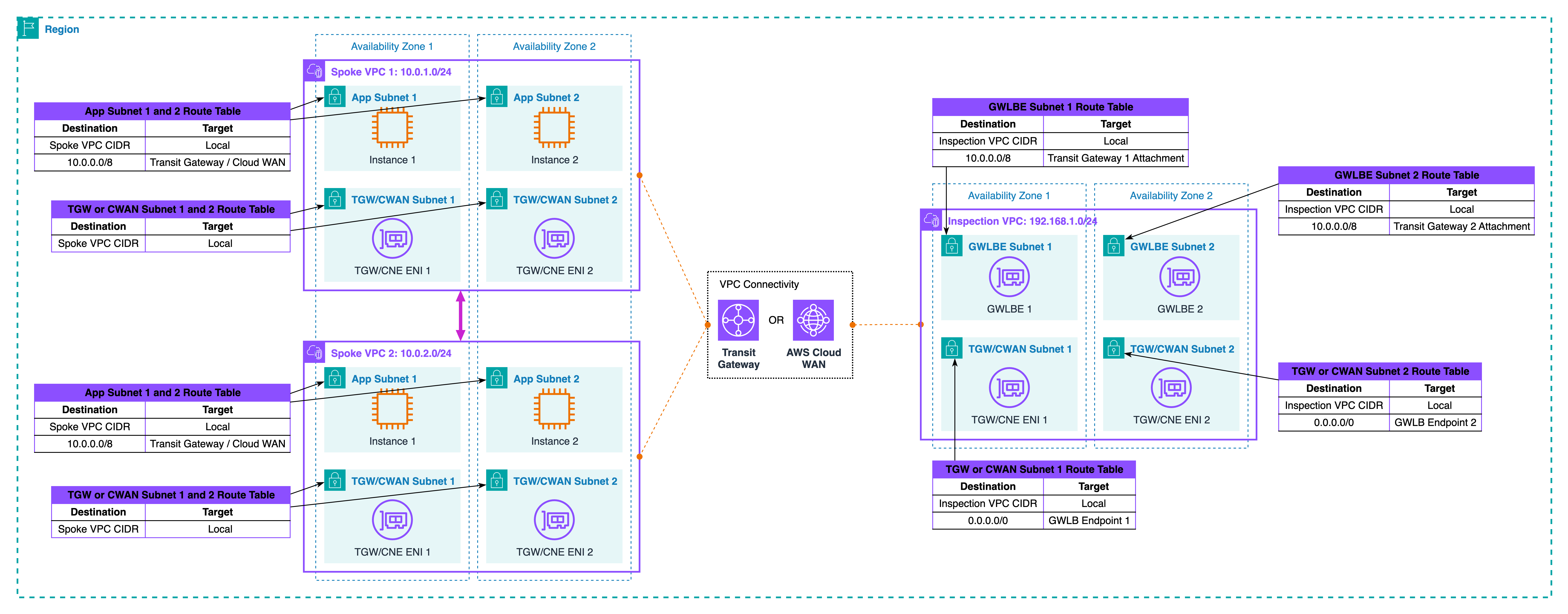
At the TGW level, there are two decisions. The Spoke VPCs route table is associated to all spoke attachments and contains a single catch-all next hop that points to the Inspection VPC attachment. Think of it as “everything not local goes to inspection first.” The Inspection VPC route table is associated to the inspection attachment and contains specific prefixes for each spoke CIDR that point to the matching spoke attachment. With this split, TGW forces every cross-VPC packet into the Inspection VPC, then forwards it to the right destination only after the device allows it.
Zonal placement and scale-out
Keep everything zonal. In the Inspection VPC, create one GWLB endpoint per AZ and attach your appliance fleet behind GWLB. In the same AZ, create the TGW subnets that host the attachment ENIs. Now, a packet that arrived from Spoke A in AZ1 can hit the AZ1 GWLB endpoint, pass the device, and return to TGW on the AZ1 attachment. That keeps latency low and avoids cross-AZ charges. GWLB health checks remove bad appliances automatically. If you use Network Firewall, place the firewall endpoints per AZ and let the service scale, but keep the same zonal idea. Centralizing inspection also simplifies logging: one place for device logs, one place for packet telemetry, and one change point for new controls.
Where symmetry fails
Without extra settings, TGW does not know you have a stateful hop in the middle. Forward and return can use different attachment ENIs or even different AZ paths. Symptoms look random: some sessions work, others reset; logs show only one direction on the device; troubleshooting wastes time. The most common cause is that the forward path enters TGW on one AZ and exits on another, while the return takes a different combination. Another cause is steering one direction into the Inspection VPC and letting the return side bypass it. You must treat symmetry as a design rule, not an afterthought.
Restoring symmetry
Turn on TGW appliance mode for the Inspection VPC attachment and use AZ affinity. Appliance mode pins a flow to a single TGW ENI, so both legs keep the same next hops. AZ affinity keeps the path inside one AZ whenever possible. Combine this with your zonal endpoints: Spoke A in AZ1 should hit the AZ1 GWLB endpoint or NFW endpoint and return to TGW on the AZ1 side. Spoke B in AZ1 should do the same when sending back. Inside GWLB, you can scale appliances up and down. The endpoint remains the insertion point, so symmetry holds even during failover. Only an AZ outage changes the map, and in that case, your application failover plan should move the session to a healthy AZ.
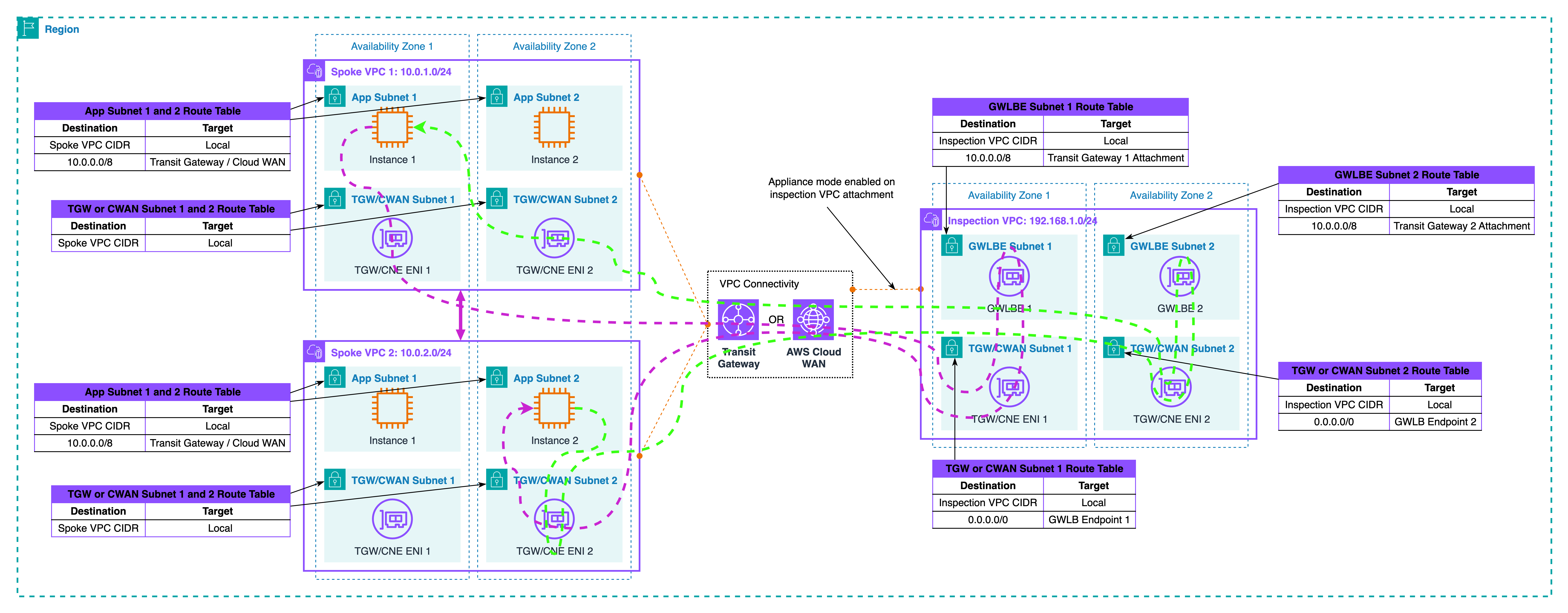
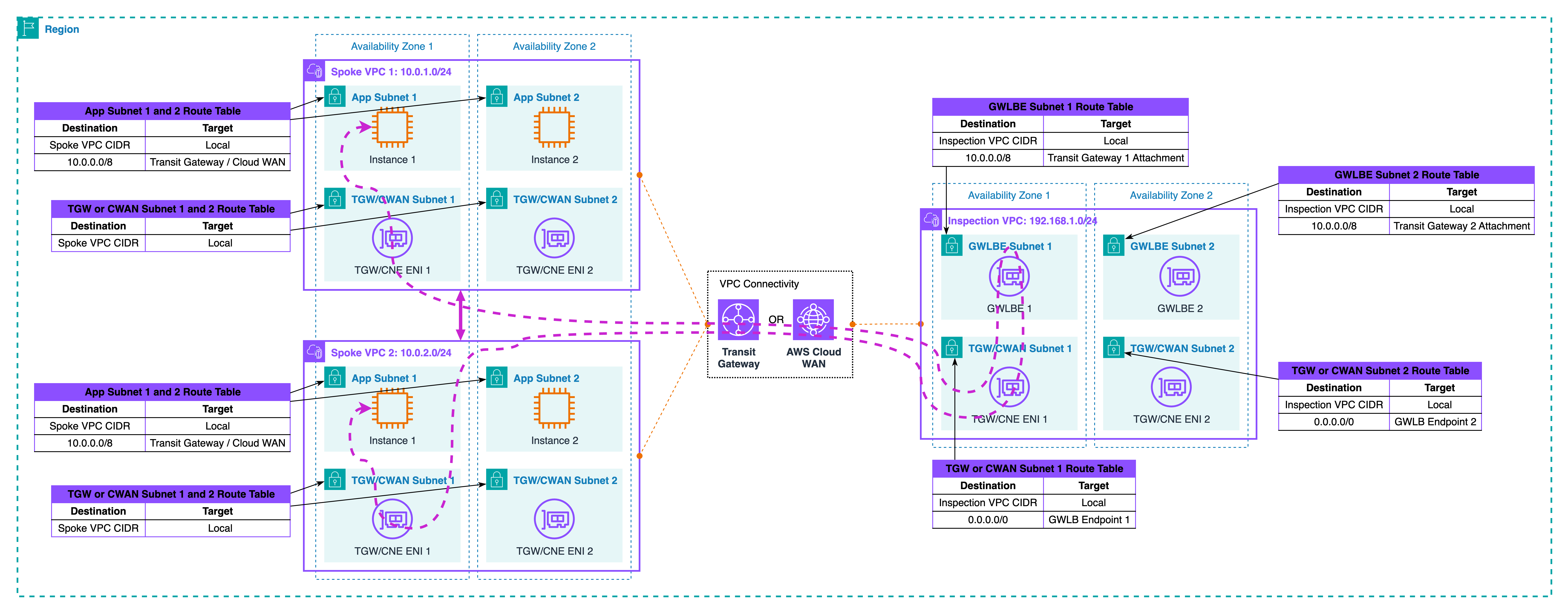
Traffic walk-through
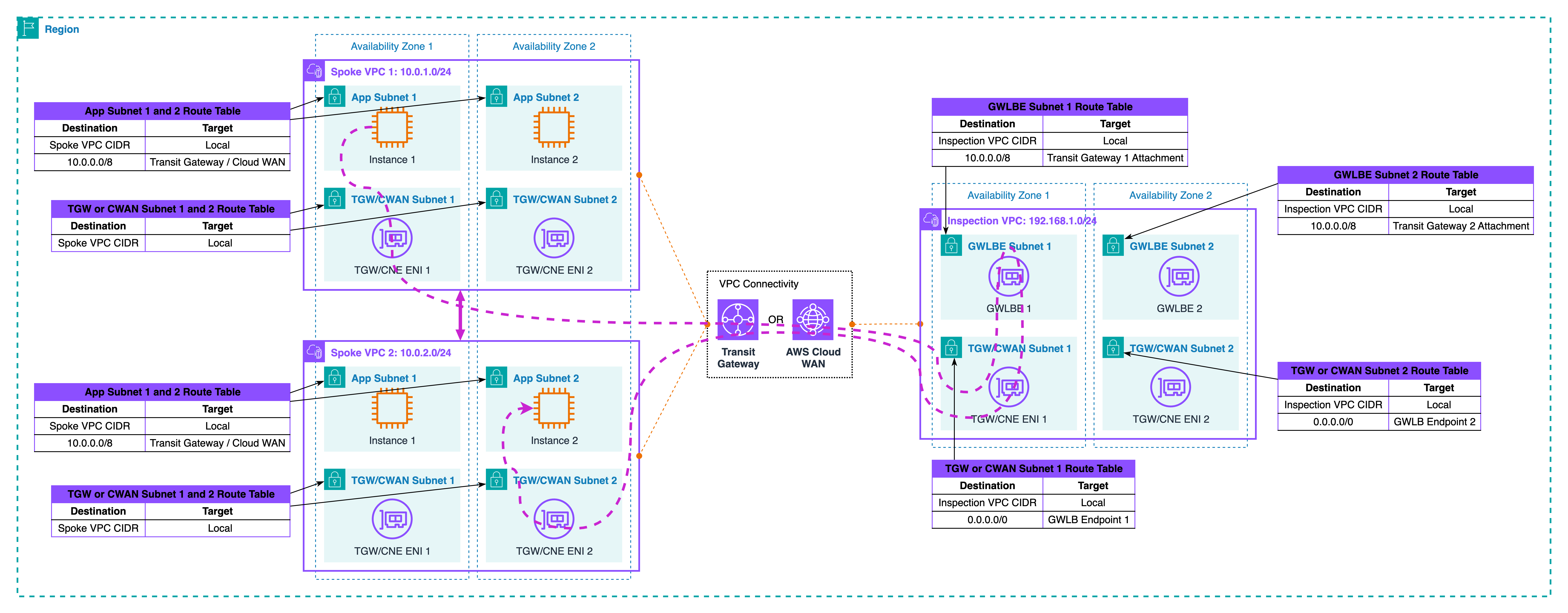
Let’s trace the traffic together as illustrated in the diagram above. Start in Spoke VPC 1, AZ1. A workload sends to a workload in Spoke VPC 2, AZ1. The spoke’s routing plan hands the packet to TGW. The packet hits the Spoke VPCs route table and is sent to the Inspection VPC attachment. In the Inspection VPC, the packet reaches the AZ1 GWLB endpoint and is passed to a healthy appliance. The device applies policy and sends the packet back to TGW on the same AZ1 attachment. Now TGW uses the Inspection VPC route table and forwards the packet to the Spoke VPC 2 attachment. The target receives it. The reply follows the same chain in reverse and, because appliance mode is on, it returns through the same AZ1 insertion point. The device sees one bidirectional session and keeps state cleanly.
If an appliance dies, GWLB stops using that instance. The endpoint stays the same, so the path does not change. If the whole AZ1 fails, traffic for that pair must move to AZ2. Your route design and health checks should make that a controlled event, not a surprise hairpin.
Cloud WAN note
You can build the same centralized model with Cloud WAN. Instead of hand-managing TGW route tables, you define segments and a network function group that represents the inspection service. A policy then sends traffic between spoke segments into the inspection segment first, and only then to the destination segment.
Choose Cloud WAN when you have many accounts and Regions, want policy-driven insertion, and need fewer per-VPC changes. Choose TGW when you want fine control at the attachment level inside one Region, or when your org already uses TGW everywhere and you prefer incremental change.
Placement decisions in inter-VPC paths
Start with the question you asked in Part 2 as well: what identity do you need to see, and where are you willing to decrypt TLS. If you place inspection before a load balancer in the spoke, the device sees the real client IP and the untouched TLS session. That is helpful for reputation rules and geo policy, but decryption here means handling public certificates on the inspection tier. If you place inspection between the load balancer and its targets, you only look at accepted traffic and you can use private certificates for decryption. With ALB the client IP is carried in X-Forwarded-For, not on the packet source. With NLB the source IP is preserved, so post-NLB placement still has client identity at L3. Choose the spot that matches your control goal, and be explicit in the diagram and text so teams do not move it by accident.
Keep the data path zonal. Put TGW attachment subnets and GWLB or Network Firewall endpoints in the same AZs as the workloads. Then pin flows to those AZs using TGW appliance mode. This is the shape shown in Diagram 3 and enforced in Diagram 5. Zonal design lowers latency, avoids cross-AZ charges, and makes failure behavior predictable. If an AZ fails, you shift to another AZ by design rather than by surprise.
Watch how the spoke’s internet edge interacts with east-west routing. Many spokes already have a default route to an IGW or to a NAT gateway for egress. East-west needs more specific prefixes for peer VPC CIDRs toward TGW, so these flows do not hairpin to the internet or to NAT. Keep those specific entries small and stable. When you add new spoke CIDRs, update the prefix source of truth and regenerate routes so the TGW path always wins over the internet default.
Choose the inspection tier that matches your operations model. Gateway Load Balancer with third-party appliances gives you transparent scale-out and health-based failover behind a stable endpoint. AWS Network Firewall gives you a managed stateful engine, built-in logging, and policy distribution with Firewall Manager. Both work in this centralized model. The important part is that the endpoint in the Inspection VPC is the insertion point. Backends can change without changing the path selection.
Mind security boundaries around TGW and endpoints. TGW attachment ENIs do not use security groups; subnet NACLs and the device do the filtering. Keep NACLs simple and deterministic, and put the detailed policy on the inspection tier. On the spoke side, security groups continue to protect workloads and should allow only what the target actually needs after inspection.
Check Maximum Transmission Unit (MTU) and Maximum Segment Size (MSS) early. GWLB uses encapsulation between the GWLB endpoint and the appliance fleet. That adds overhead. In most VPCs, it works out of the box with path MTU discovery, but if you see sporadic stalls, clamp TCP MSS on the device or on the relevant path so large packets do not fragment silently.
Avoid overlapping CIDRs between spokes. TGW does not fix overlaps for you. If you must connect overlapping spaces, you will need NAT or a translation layer, which changes how you log and how you attribute traffic. Treat that as a separate design, not a quick tweak to this pattern.
Finally, keep naming and tagging consistent so placement is obvious in logs and diagrams. Tag TGW attachments, endpoint subnets, and appliances with the AZ and role. When you read device logs later, you can tell at a glance which AZ handled a flow and whether it matched the intended insertion point.
Validation without route tables
You can prove the centralized pattern works without dumping a single route table. Validate the shape, the path, the symmetry, and failure behavior using tools and logs.
- Start with shape. In the TGW console, check associations only. All spoke attachments must be associated to the Spoke VPCs route table. The Inspection VPC attachment must be associated to the Inspection VPC route table. Do not open the routes. You are only confirming the attachment-to-table mapping. On the Inspection VPC attachment, confirm Appliance mode: enabled. This flag pins flows to a single TGW ENI. Record which AZ each TGW attachment ENI lives in and which AZ each GWLB endpoint or Network Firewall endpoint lives in.
- Next, prove the path with a reachability test. From a source ENI in Spoke VPC 1 AZ1, run VPC Reachability Analyzer to a target ENI in Spoke VPC 2 AZ1. The expected path is: Spoke 1 → TGW → Inspection VPC attachment → GWLBE or NFW endpoint in AZ1 → device → back to the same TGW attachment → TGW → Spoke 2. Save the visualization as evidence. Repeat from AZ2 to AZ2. If your spokes use ALB or NLB, run one test to a target behind the balancer and confirm the hop sequence still includes the inspection endpoint before the packet reaches the target’s subnet.
- Now check runtime symmetry on the device side. For GWLB-based appliances, look at session logs on the firewall and the endpoint ID in GWLB telemetry. You want to see both directions of the same five-tuple on the same endpoint and in the same AZ. For Network Firewall, read flow logs and confirm that a connection from Spoke 1 to Spoke 2 appears as one bidirectional flow with the same endpoint AZ. Add one connection in each direction to make the test explicit: A→B and B→A should both hit the same AZ1 endpoint when the instances live in AZ1.
- Observe the hub while traffic flows. Enable Transit Gateway flow logs and filter for the spoke attachment IDs. You should see packets arriving on a spoke attachment, then on the inspection attachment, then leaving on the other spoke attachment. The count should rise in both directions during your test. In CloudWatch for GWLB endpoints, watch processed bytes and health metrics for the AZ1 endpoint while you run the A↔B test in AZ1. For Network Firewall, watch the
BytesProcessedandPacketsProcessedmetrics for the AZ1 endpoint during the same test window. - Run a simple failure drill to prove stability. If you use GWLB, drain one appliance from the target group in AZ1. Existing sessions should continue or re-establish through a healthy instance, and new sessions should still enter via the same GWLB endpoint. The insertion point does not change. For Network Firewall, reduce capacity on the AZ1 endpoint and verify that traffic is throttled or load-shifted by the service without the endpoint ID changing. In both cases, your logs must still show the same endpoint and the same TGW inspection attachment on both legs.
- Test AZ pinning. Create two short-lived flows at the same time, one AZ1 to AZ1, one AZ2 to AZ2. Confirm that the AZ1 flow uses the AZ1 inspection endpoint and the AZ1 TGW ENI, while the AZ2 flow uses the AZ2 counterparts. If either flow crosses to the other AZ, revisit appliance mode and your endpoint placement. Zonal drift now will become cost and latency later.
- Do one negative test to catch accidental bypass. From Spoke 1, try a destination in Spoke 2 that is not in your allow list on the device. You should see the attempt arrive at the inspection tier and drop there. You should not see a direct TGW pass from spoke to spoke in the TGW flow logs. If you do, the centralized insertion is not complete.
- Finish with a tiny checklist in your runbook: attachment associations look right, appliance mode enabled, endpoints present per AZ, A↔B reachability shows the inspection hop, device logs show both directions on one endpoint, TGW logs show the spoke → inspection → spoke sequence, failure drill preserves the insertion point, and az-to-az tests stay local. If all checks are green, your centralized path is working exactly as designed.
Observability and cost watch-outs
For observability: enable decision logs on the inspection tier and tie them to the network path. For GWLB, keep appliance logs plus endpoint metrics; for Network Firewall, use flow and alert logs. Turn on Transit Gateway flow logs to see packets arrive on a spoke attachment, traverse the inspection attachment, then exit to the other spoke; add VPC Flow Logs on the subnets that host TGW ENIs and the GWLB or NFW endpoints. Use one schema everywhere: five-tuple, decision, endpoint ID, attachment ID, AZ, and a request or trace ID if a load balancer sits in the path. Tag attachments and endpoints with AZ and role, and include those tags in logs. Build a small dashboard that shows per-AZ endpoint throughput, accept/drop ratio, and a symmetry health check that alerts when forward packets appear on an endpoint without matching returns on the same endpoint. Add canary probes A↔B per AZ and fail them if the observed endpoint or AZ is not what you expect.
This centralized pattern touches TGW twice per flow, so you pay TGW data processing in both directions; GWLB adds per-GB processing, and Network Firewall adds endpoint hours plus traffic. Inter-AZ hops add transfer cost, so keep TGW attachments and inspection endpoints zonal and pin flows with appliance mode.
Logs also cost money: CloudWatch ingestion and storage grow fast. Keep high-value decision logs longer, export older logs to S3, and reduce verbosity where you are not using the signal.
Also, I highly recommend to review per-AZ volumes on TGW and GWLB: if one AZ is consistently high without reason, it usually points to placement or symmetry drift that wastes budget.
What’s next
This post focused on inter-VPC pattern within centralize mode in the same Region. In next blog post, we leave a single Region and take the same centralized idea across Regions. We will connect spoke VPCs through TGW inter-Region peering or Cloud WAN, decide where inspection lives at the Region boundary, and show when double inspection is the right choice.
For additional learning, check out the AWS Well-Architected Framework Security Pillar and AWS Security Best Practices for network security guidance.